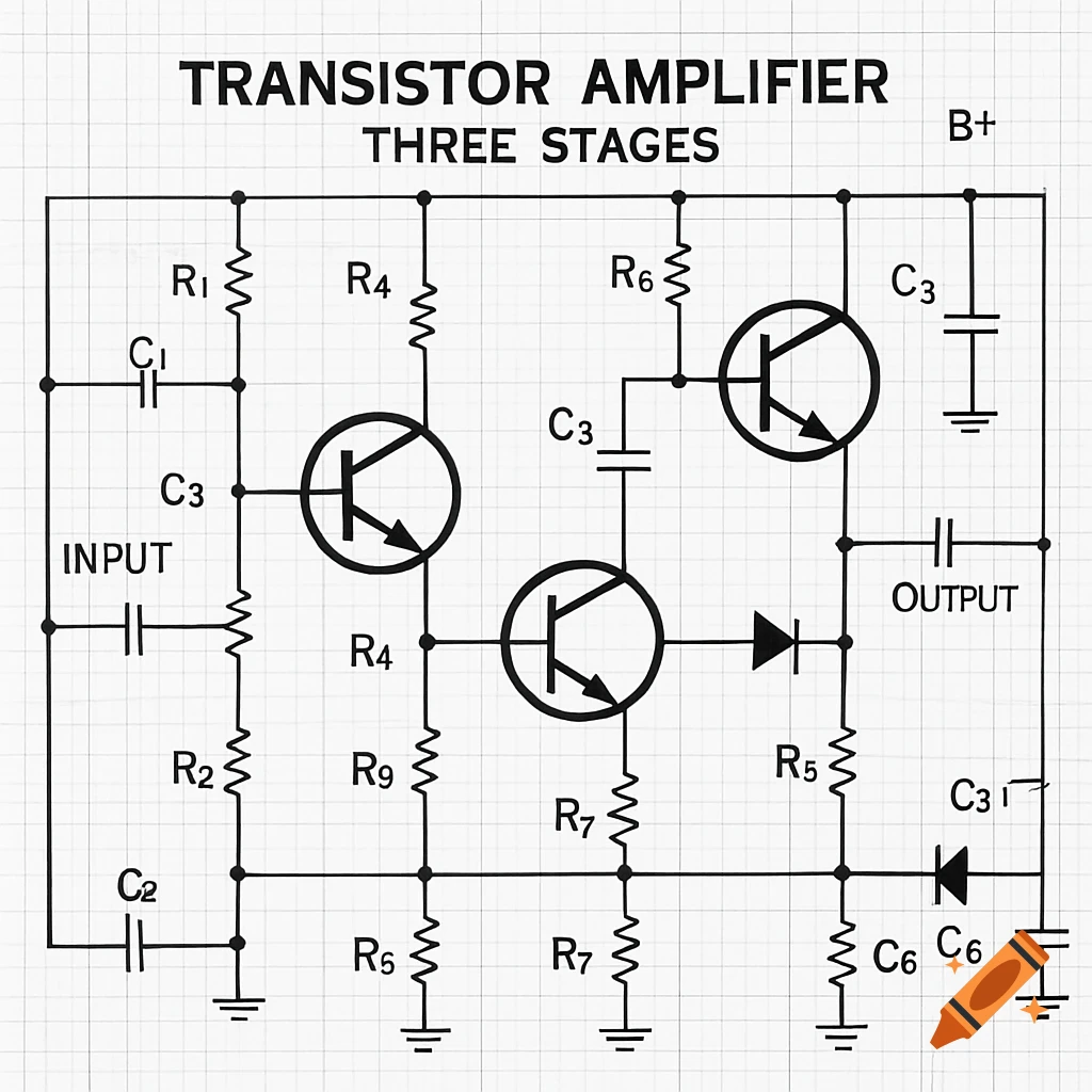
A black and white electronic schematic diagram for an inductive sensor amplifier, featuring resistors, a diode, transistors, and an optocoupler, with labeled component values and connections.
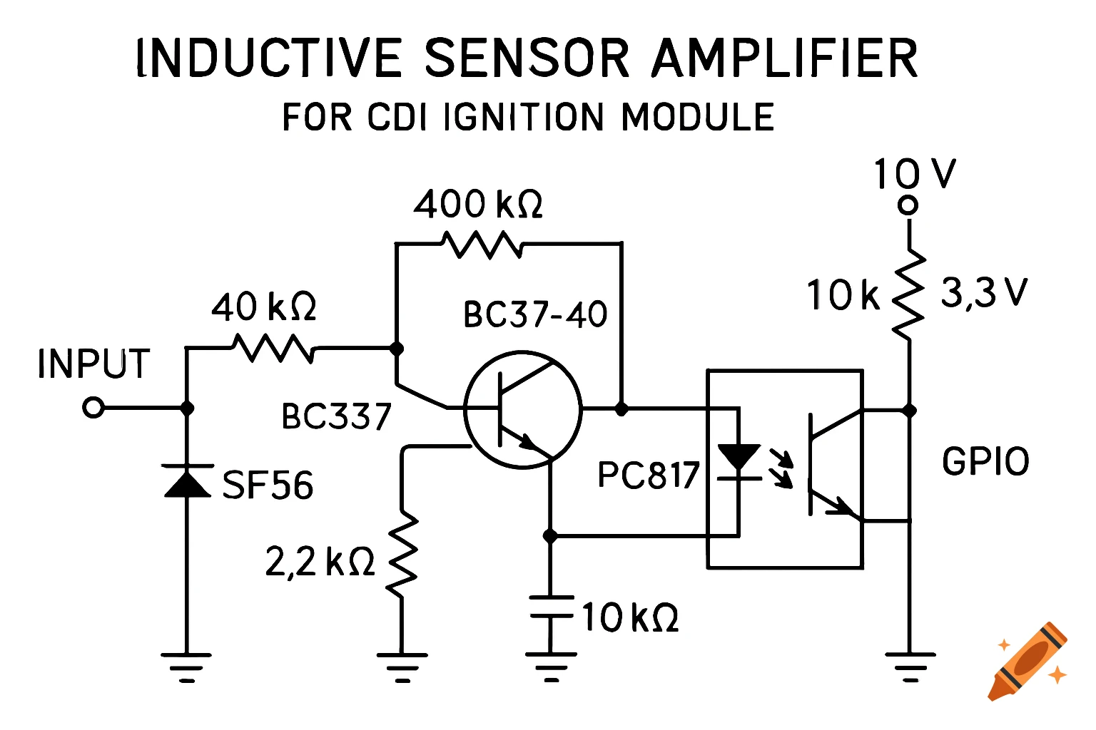
Draw a clear, professional electronic schematic diagram of an inductive sensor amplifier for a CDI ignition module. The components include: NPN transistor BC337-40 with collector, base, and emitter labeled Optocoupler PC817 with LED input (anode and cathode) and transistor output (collector and emitter) Resistors: 400 kΩ (base pull-up), 40 kΩ (base to ground), 2.2 kΩ (LED current limiting), 10 kΩ (output pull-up) Capacitor 100 nF coupling input signal Diode SF56 in series with the input signal Show all connections: Transistor emitter to ground Collector connected to PC817 LED anode through 2.2 kΩ resistor LED cathode to ground Collector of PC817 output pulled up to 3.3 V via 10 kΩ resistor, connected to microcontroller GPIO Input signal connected to base via 100 nF capacitor and diode Use standard electronic schematic symbols, labels for all pins and components, clean layout with readable wire connections, no 3D rendering, top-down view, black-and-white style, high clarity, professional schematic style.” See more