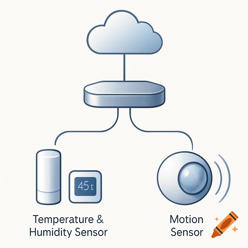
A clean system design diagram showing a Sensor Node (Arduino Nano) connected via BLE to a Gateway (Arduino RP2040), which then connects to a PC, Tablet, and Smartphone via WebSockets and HTTP/HTTPS.
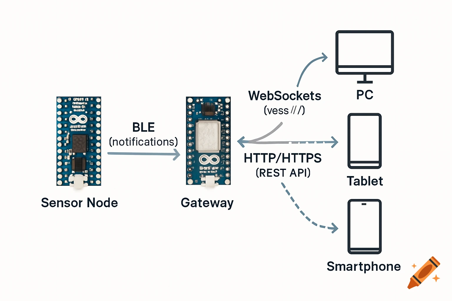
Create a clean, professional system design diagram for an academic thesis. Elements: On the left bottom: an Arduino Nano 33 BLE Sense board (labeled clearly). In the center: an Arduino RP2040 Connect board (labeled clearly, this is the gateway). On the right side: three client devices — a PC, a tablet, and a smartphone (use simple modern icons, each labeled). Connections (with arrows and labels): From Nano 33 BLE Sense → RP2040 Gateway: arrow labeled “BLE (notifications)” — this shows the sensor sending data via Bluetooth Low Energy. From RP2040 Gateway → PC/Tablet/Smartphone: arrows labeled “WebSockets (wss://)” — showing real-time two-way communication with clients. Optionally, also add a dashed arrow from RP2040 Gateway → clients labeled “HTTP/HTTPS (REST API)” to indicate configuration access. Style: Minimalist, academic, professional. Soft neutral background (white or light grey). Use simple colors (blue/black/grey) and keep it easy to read. Rounded arrows with clear text labels above each. No extra devices (only 2 boards and 3 clients). The final diagram should look simple but clear enough to be used in both a thesis document and a presentation slide. It should provide an overview of the system, so each arrow can later be described in detail during the chapter. See more