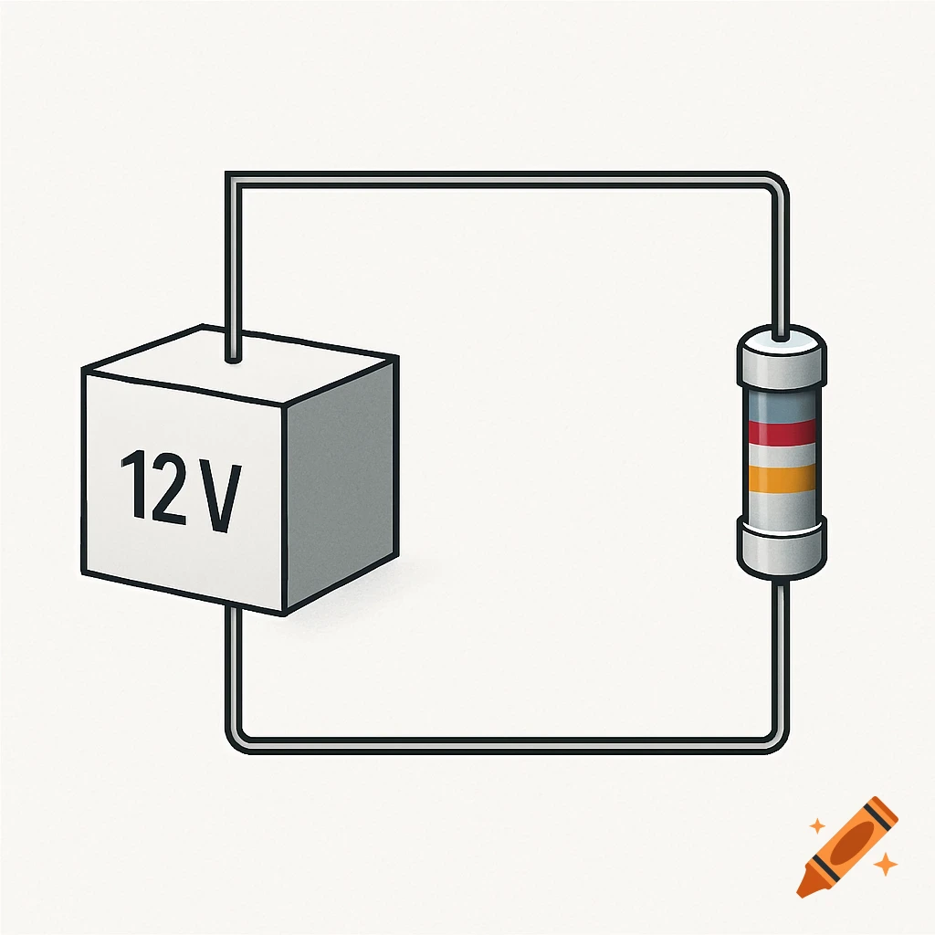
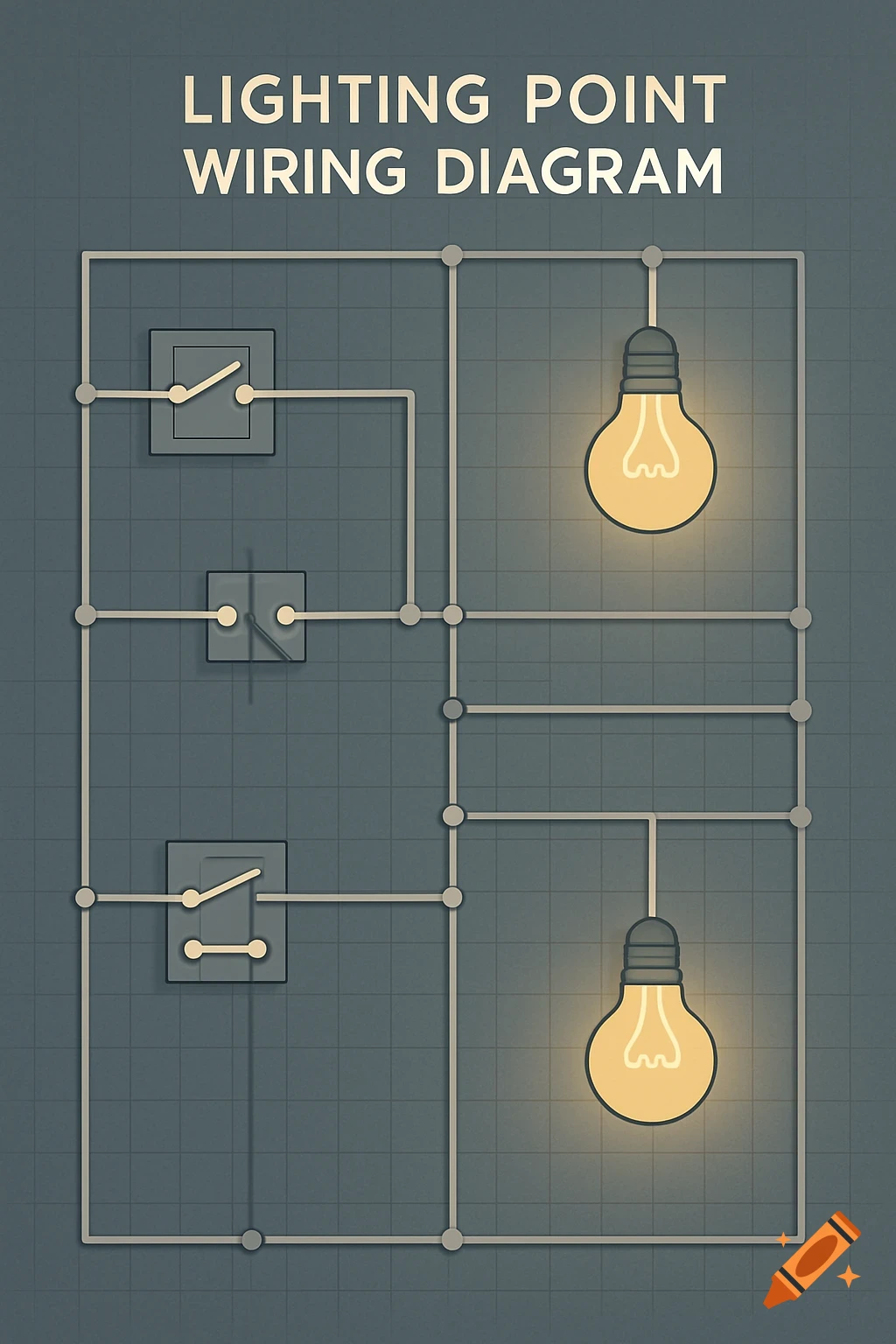
A circuit diagram showing a 12V DC power supply connected to a fuse, a momentary switch, and two DPDT relays labeled RELAY_EXTEND and RELAY_RETRACT.
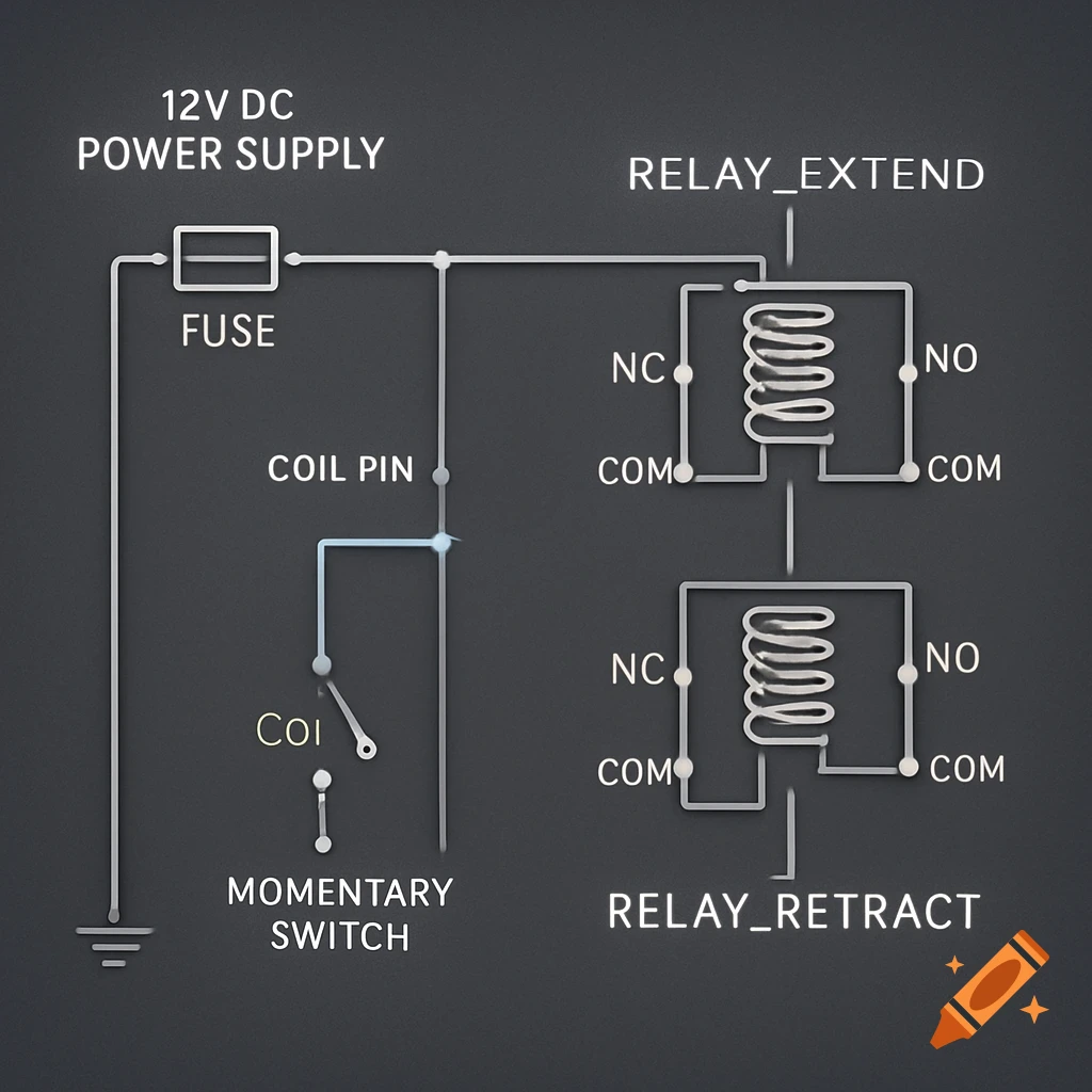
Circuit Diagram Description Since I cannot draw a visual diagram, I will describe the connections in detail. Imagine the two DPDT relays as RELAY_EXTEND and RELAY_RETRACT. Each DPDT relay has: Coil Pins: These are the pins that, when powered, switch the relay. Common Pins (COM): These are the poles that switch between two other contacts. Normally Open (NO) Pins: Connected to COM when the coil is energized. Normally Closed (NC) Pins: Connected to COM when the coil is de-energized. 1. Power Input and Protection: Connect the Positive (+) terminal of your 12VDC Power Supply to one side of the Fuse Holder. Connect the other side of the Fuse Holder to a central positive distribution point for your circuit. Connect the Negative (-) terminal of your 12VDC Power Supply to a central negative (Ground) distribution point for your circuit. 2. Relay Coil Wiring (Control Side): RELAY_EXTEND Coil: Connect one coil pin of RELAY_EXTEND to the central positive distribution point (after the fuse). Connect the other coil pin of RELAY_EXTEND to one terminal of Momentary Switch 1 (Extend - Outside). Connect the other terminal of Momentary Switch 1 (Extend - Outside) to the central negative (Ground) distribution point. Connect one terminal of Momentary Switch 2 (Extend - Inside) in parallel with Momentary Switch 1 (i.e., to the same coil pin of RELAY_EXTEND). Connect the other terminal of Momentary Switch 2 (Extend - Inside) in parallel with Momentary Switch 1 (i.e., to the central negative See more