A technical diagram shows a spaceborne SAR MAPS transmission and reception system with antenna bars, phase centers, and labels.
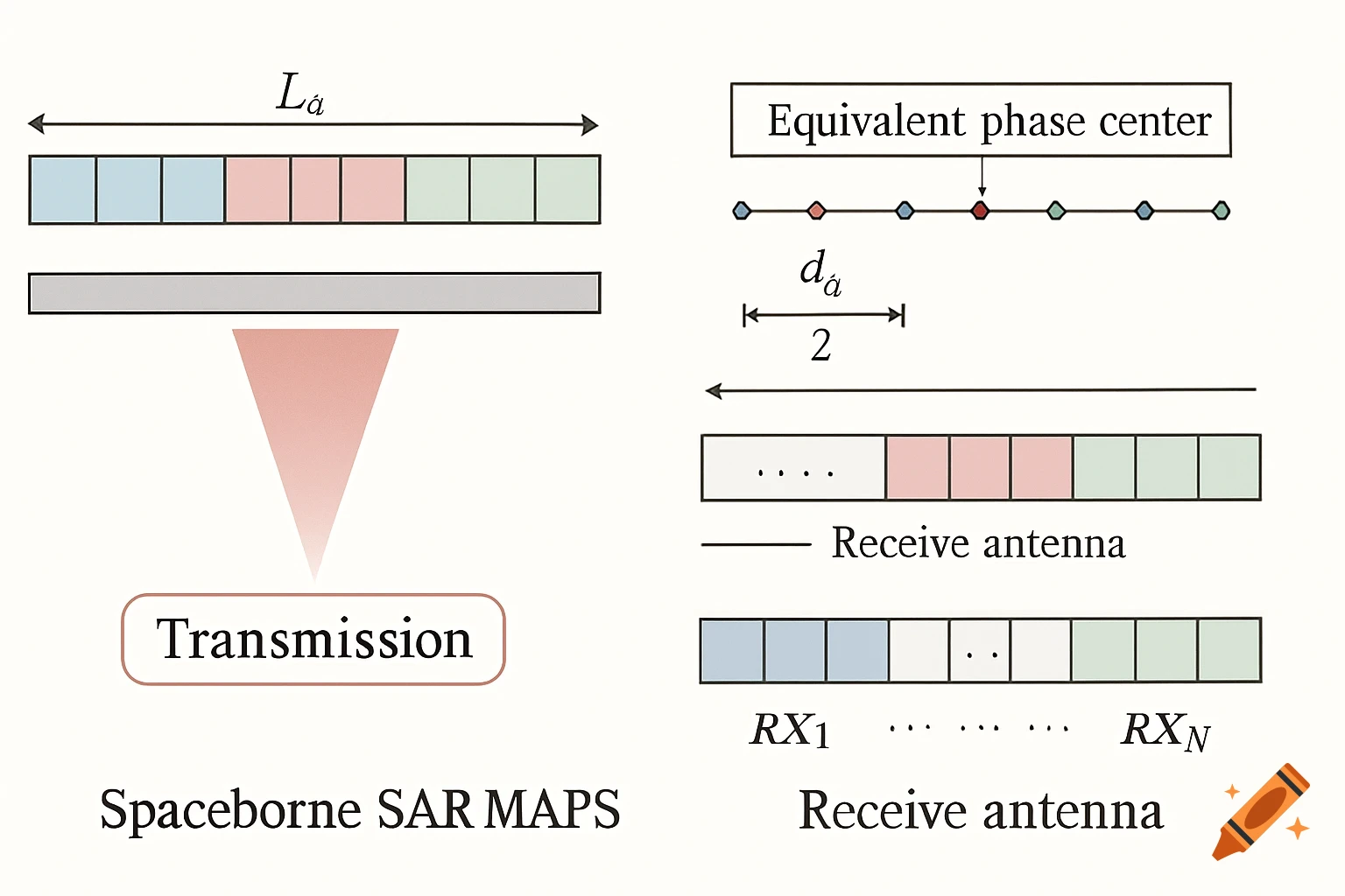
Professional proposal-style engineering schematic diagram for a spaceborne SAR MAPS (Multi-Aperture Processing Scheme). Clean white background, two panels side by side. LEFT PANEL (Transmission): Draw a long horizontal antenna bar at the top, labeled with 'Lₐ' above it and arrowheads showing the full length. The bar is divided into exactly 10 equal rectangular tiles: • first 2 tiles: light blue, • next 2 tiles: white with a small '...' label above them, • next 2 tiles (center): light red, • above these red tiles also place a small '...' label, • next 2 tiles: white with a small '...' label above them, • final 2 tiles: light green. Below the bar, draw one downward radar beam cone with a smooth red gradient, apex aligned with the center between the two red tiles. Beneath the cone, a rounded rectangle label with thin red outline and white fill, containing the word 'Transmission' in bold black text. RIGHT PANEL (Reception): At the top, draw a boxed label 'Equivalent phase center'. Below that, a horizontal line with colored dots (blue, red, green repeating) representing equivalent phase centers. Add spacing annotations 'dₐ / 2' and 'vₛ · PRI' with double-headed arrows between dots. Under that, draw a long receive antenna bar made of many small tiles. Apply a repeating color structure similar to Transmission: light blue section, white + '...', light red center, white + '...', light green end. Below the bar, label the channels 'RX1 ... RXN'. Below that, draw three partially See more