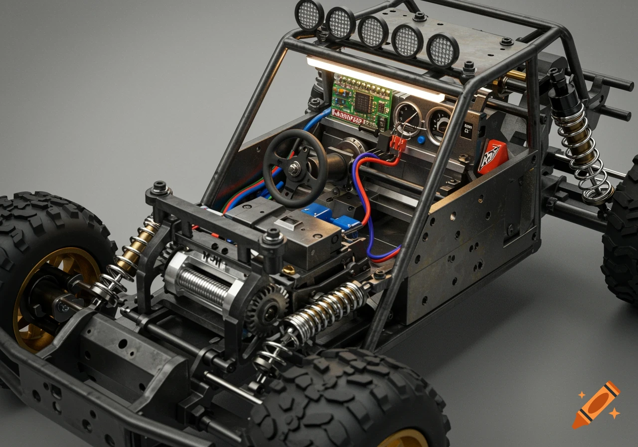
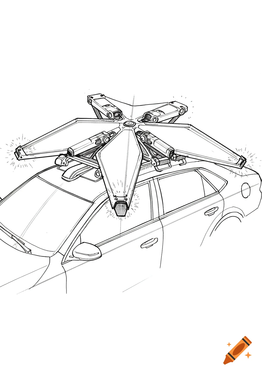
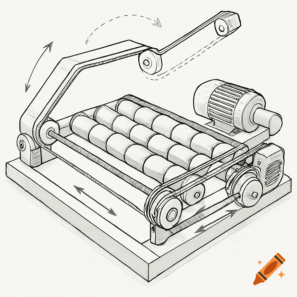
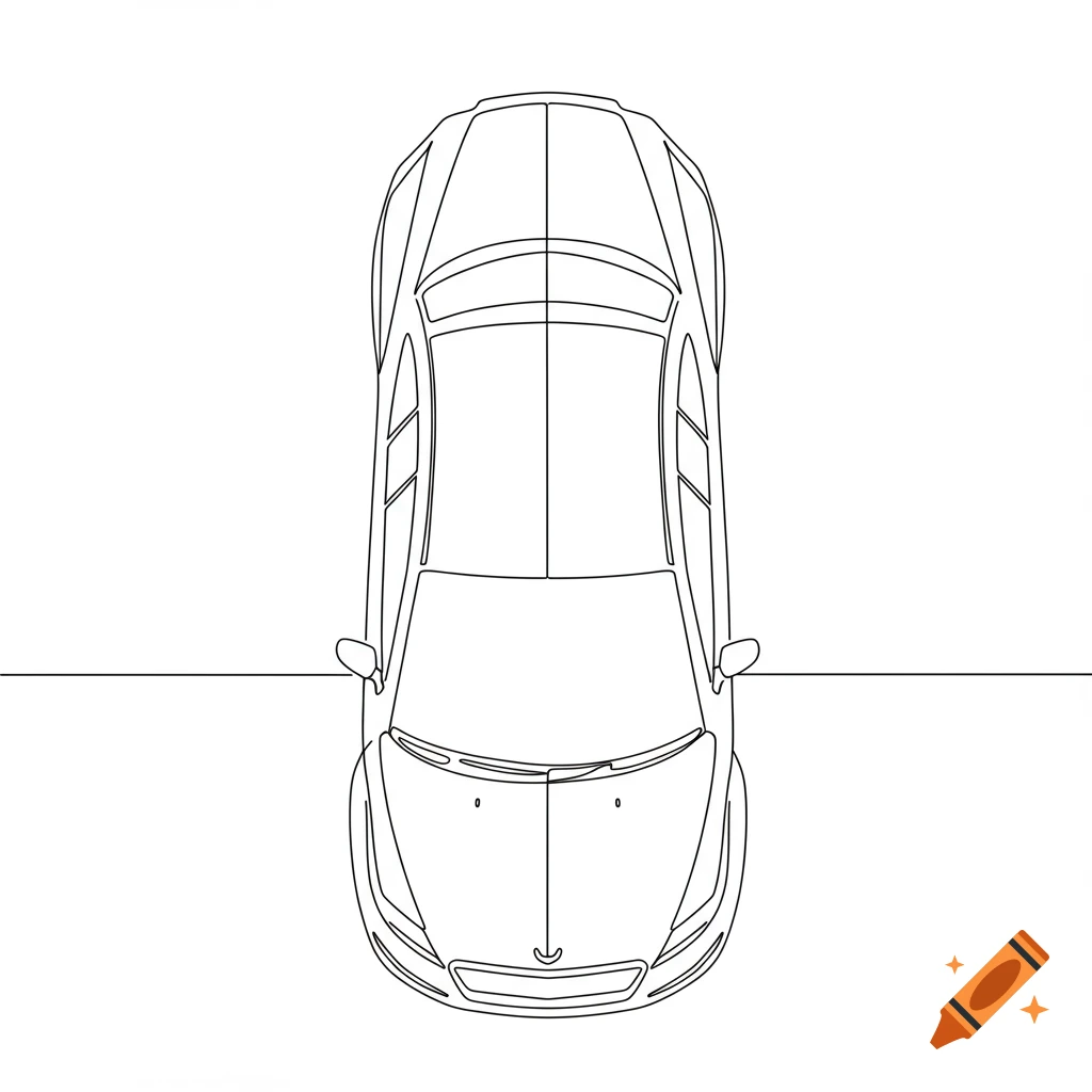
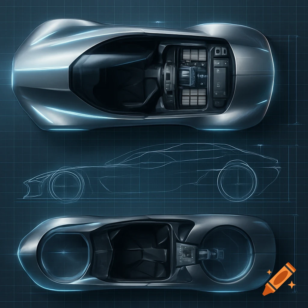
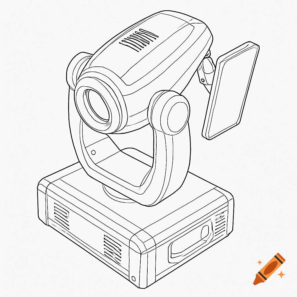
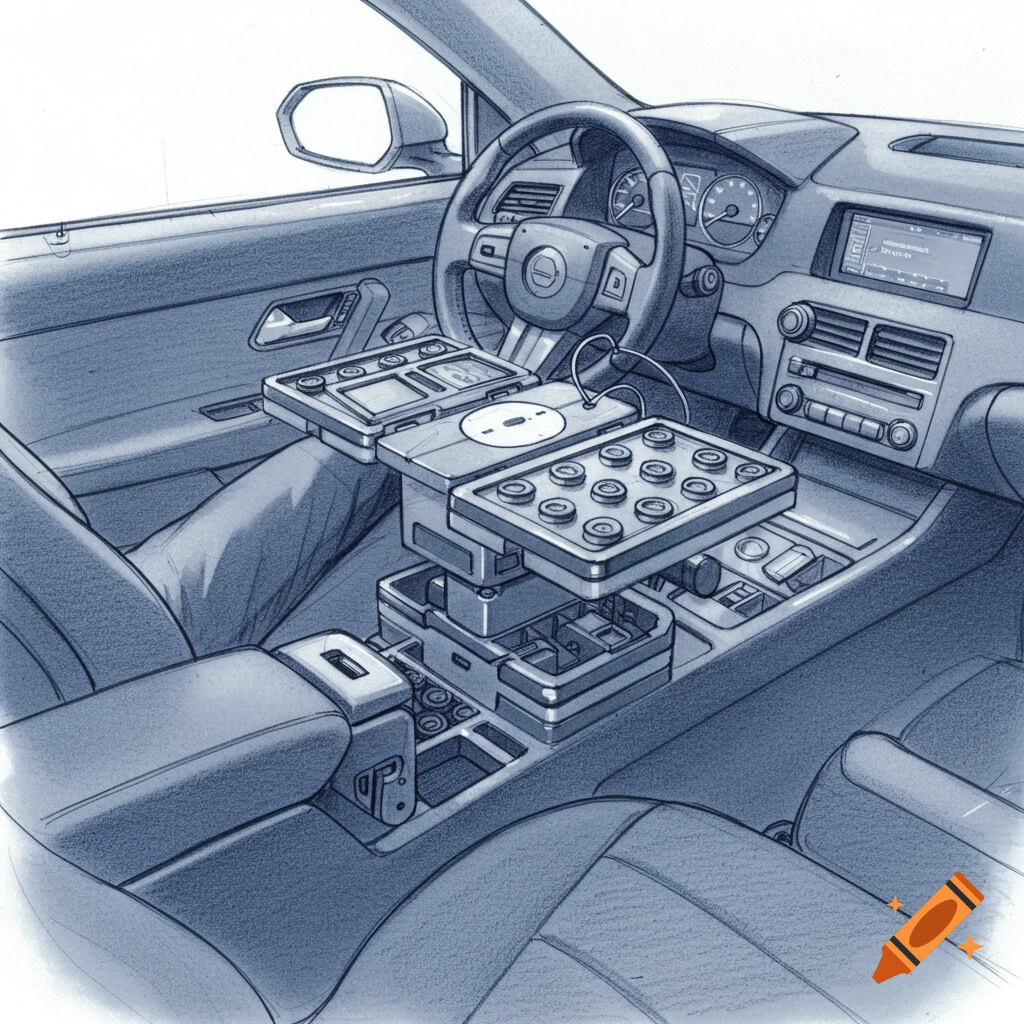
Black and white line diagram of an RC car's front section with labeled camera panning mechanism.
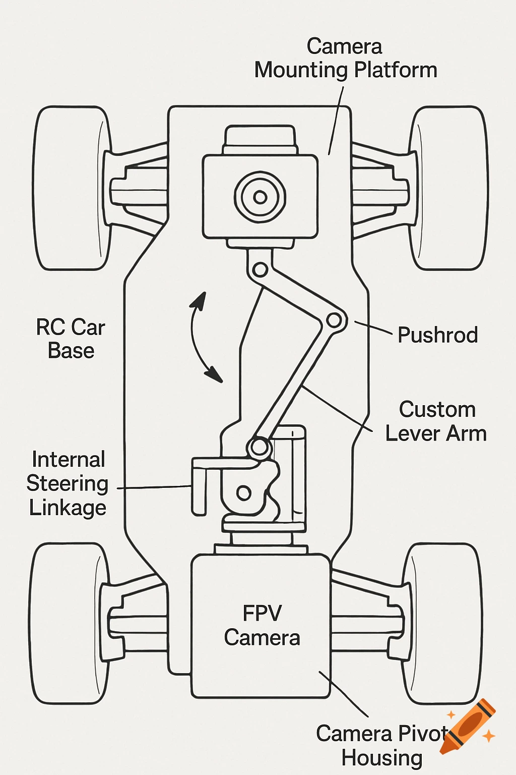
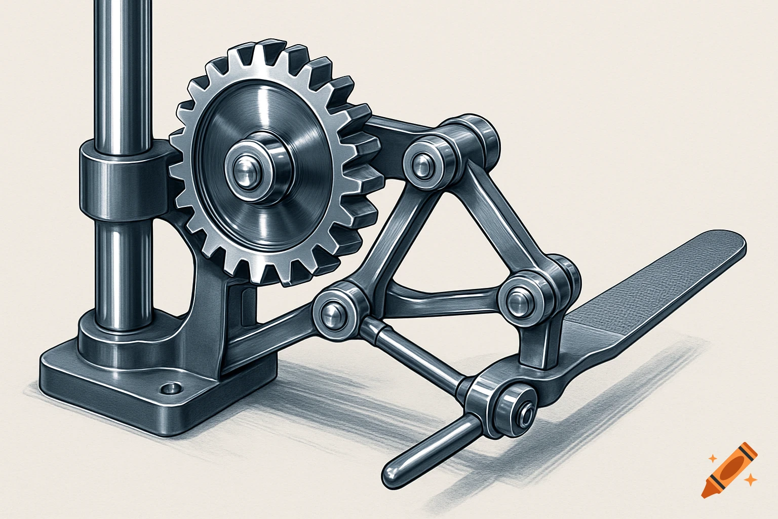
Okay, let's describe the drawing of Concept A in a way that's clear and concise, using appropriate terms, but without getting bogged down in extreme detail. The drawing of Concept A presents a top-down view of the front section of the RC car, focusing on the integrated mechanical linkage. * RC Car Base: The sketch begins with a simplified representation of the RC car's chassis, showing the front wheels and the internal steering linkage, typically including components like the servo-actuated bellcrank and tie rods. * Camera System: Positioned centrally on the chassis, ahead of the existing steering components, is the custom camera assembly. This consists of a stationary Camera Pivot Housing/Base mounted to the chassis, supporting a rotating Camera Mounting Platform. The FPV Camera is securely depicted on top of this rotating platform. * The Mechanical Linkage: The crucial element is the direct mechanical connection. A Custom Lever Arm is shown attached to a moving point on the RC car's existing steering linkage (e.g., a bellcrank arm). Extending from this Custom Lever Arm to an attachment point on the Camera Mounting Platform is a straight Pushrod. * Movement Indication: Arrows clearly illustrate the operational principle: the steering motion of the RC car causes the Custom Lever Arm to pivot, which in turn pushes or pulls the Pushrod. This linear motion is then converted into a rotational (panning) movement of the Camera Mounting Platform, allowing the camera to follow the See more