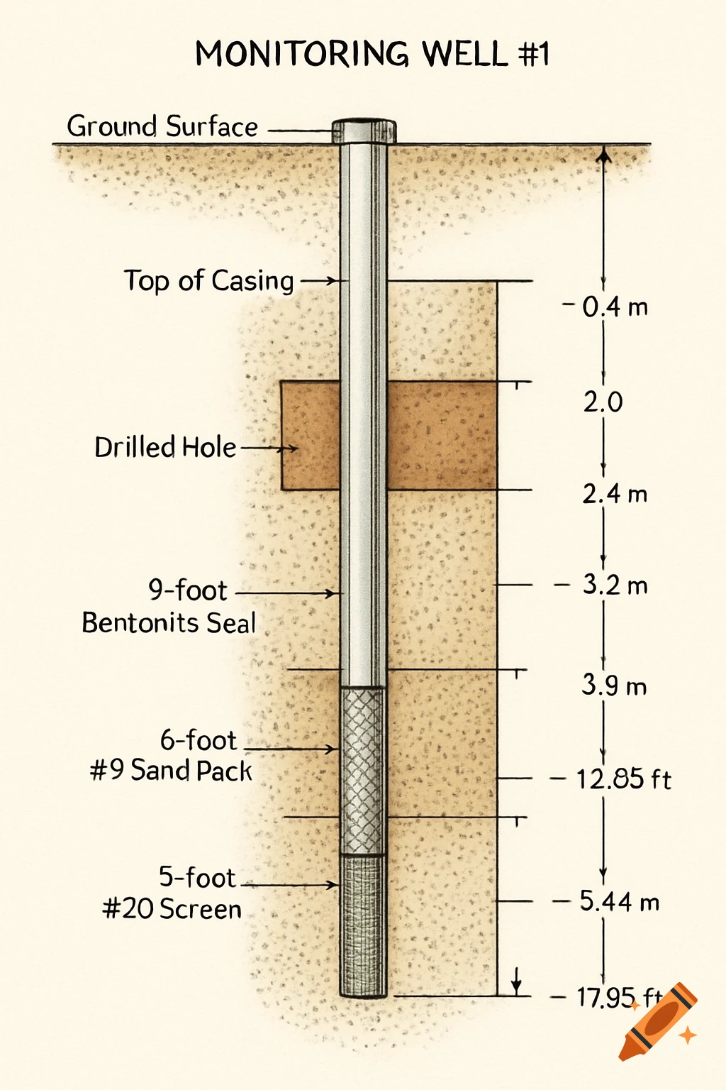
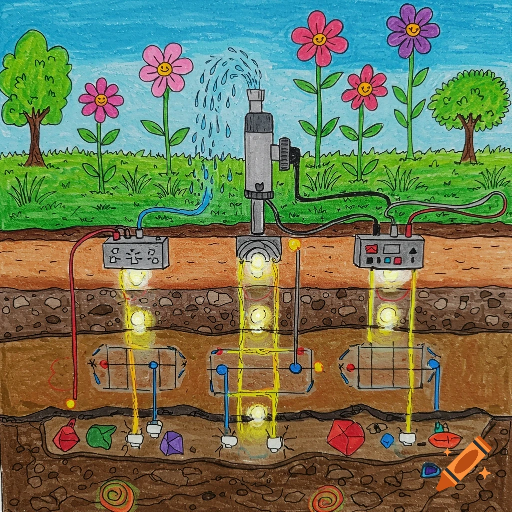
A detailed cross-section diagram of a groundwater monitoring well, showing layers of grout, bentonite, sand pack, and a well screen with measurements.
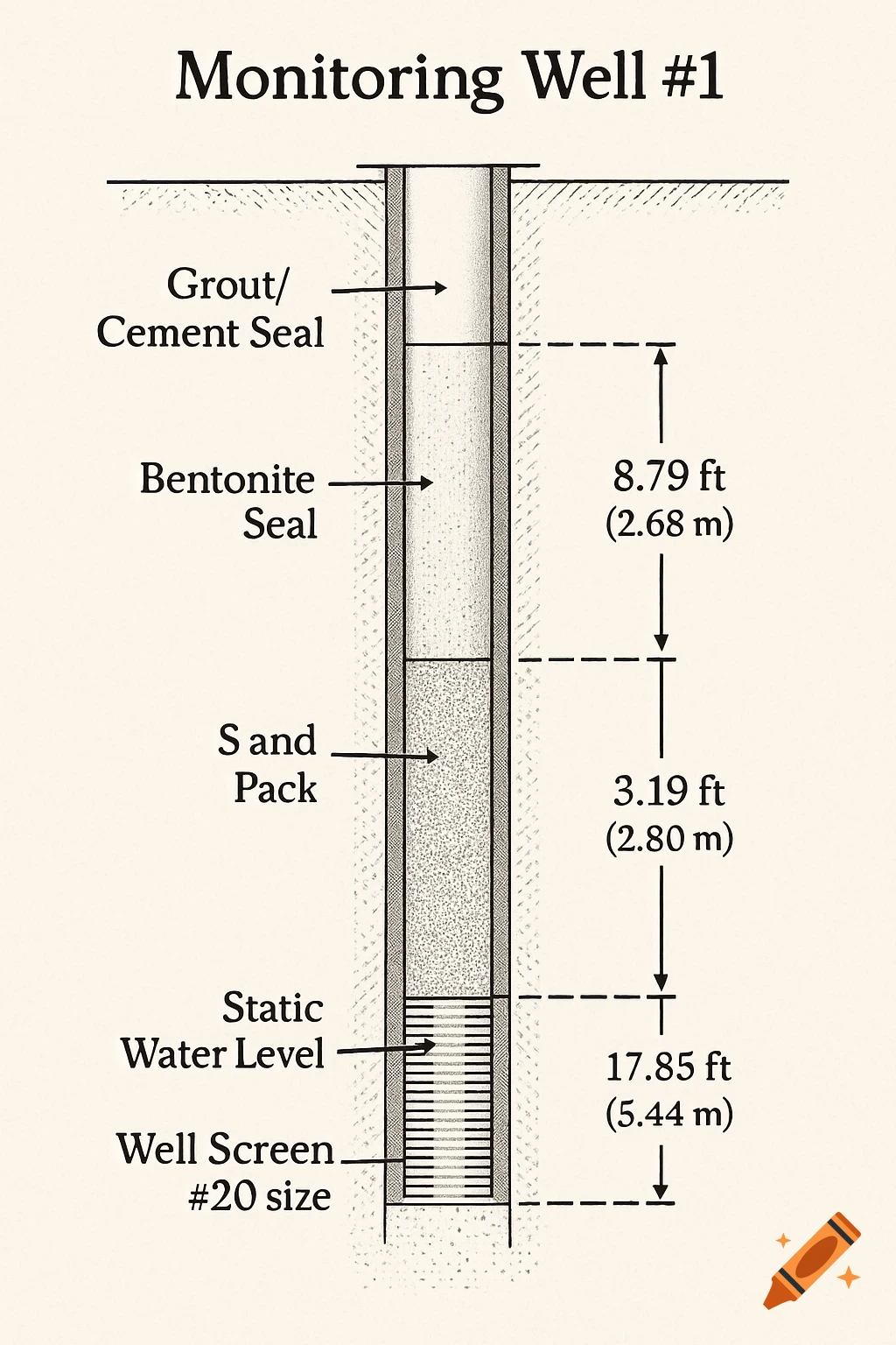
Diagram Description: Create a detailed, vertical cross-section of a groundwater monitoring well, labeled "Monitoring Well #1," with all its components and relevant measurements. Overall Dimensions: The total depth of the well is 5.44 meters (17.85 feet) below the ground surface. The borehole has an intake diameter of 4 inches throughout its entire depth. The well casing has an inner diameter of 2 inches. Components and Materials (from top to bottom): Ground Surface: A horizontal line representing the ground surface. Grout/Cement Seal: The topmost layer within the borehole, filling the space between the 2-inch casing and the 4-inch borehole from the ground surface down to a depth of approximately 8.79 ft (~2.68 m). Bentonite Seal: A 9-foot-long seal made of bentonite clay. This layer is located immediately below the grout/cement, extending from the bottom of the grout down to a depth of approximately 17.79 ft (~5.42 m). Sand Pack: A 6-foot-long layer of sand with a grain size of #9. This material surrounds the well screen and extends for 1 foot above it, from the bottom of the bentonite seal down to the total depth of the well (17.85 ft or 5.44 m). Well Screen: A 5-foot-long screen with a size of #20, situated at the very bottom of the well. This screen is embedded within the sand pack, allowing water to enter the well. Key Measurements and Labels: Static Water Level: Draw a horizontal dashed line across the well casing at a depth of 2.80 meters (9.19 feet) from the top of See more