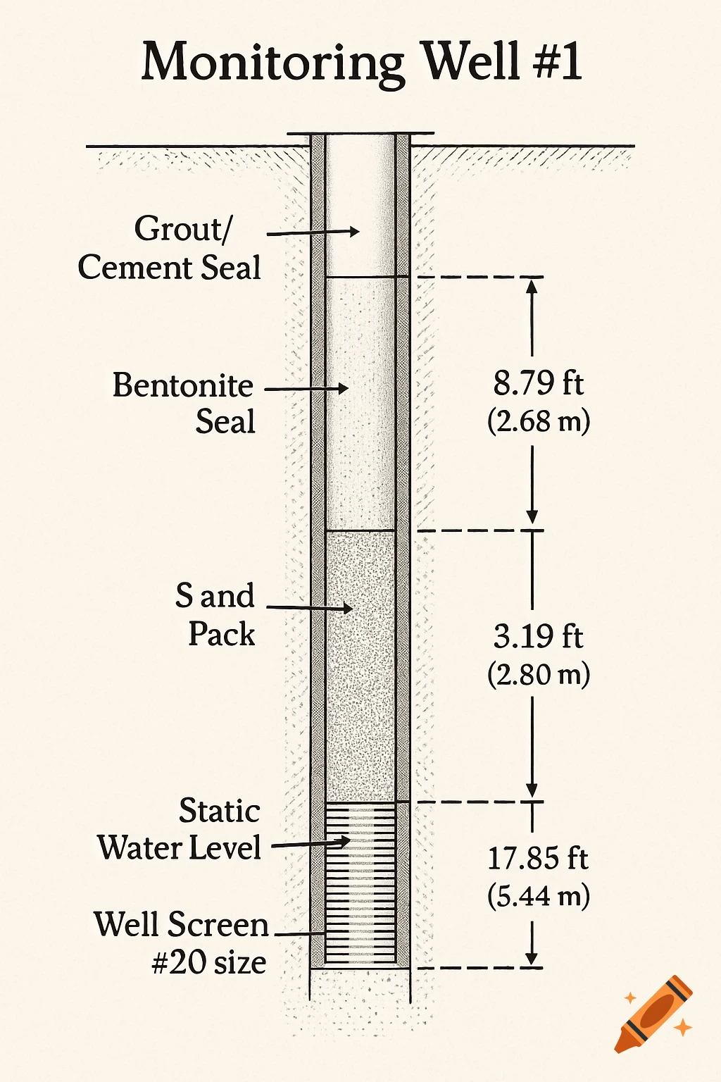
A detailed cross-section diagram of a monitoring well, showing ground surface, casing, drilled hole, bentonite seal, sand pack, and screen with depth measurements.
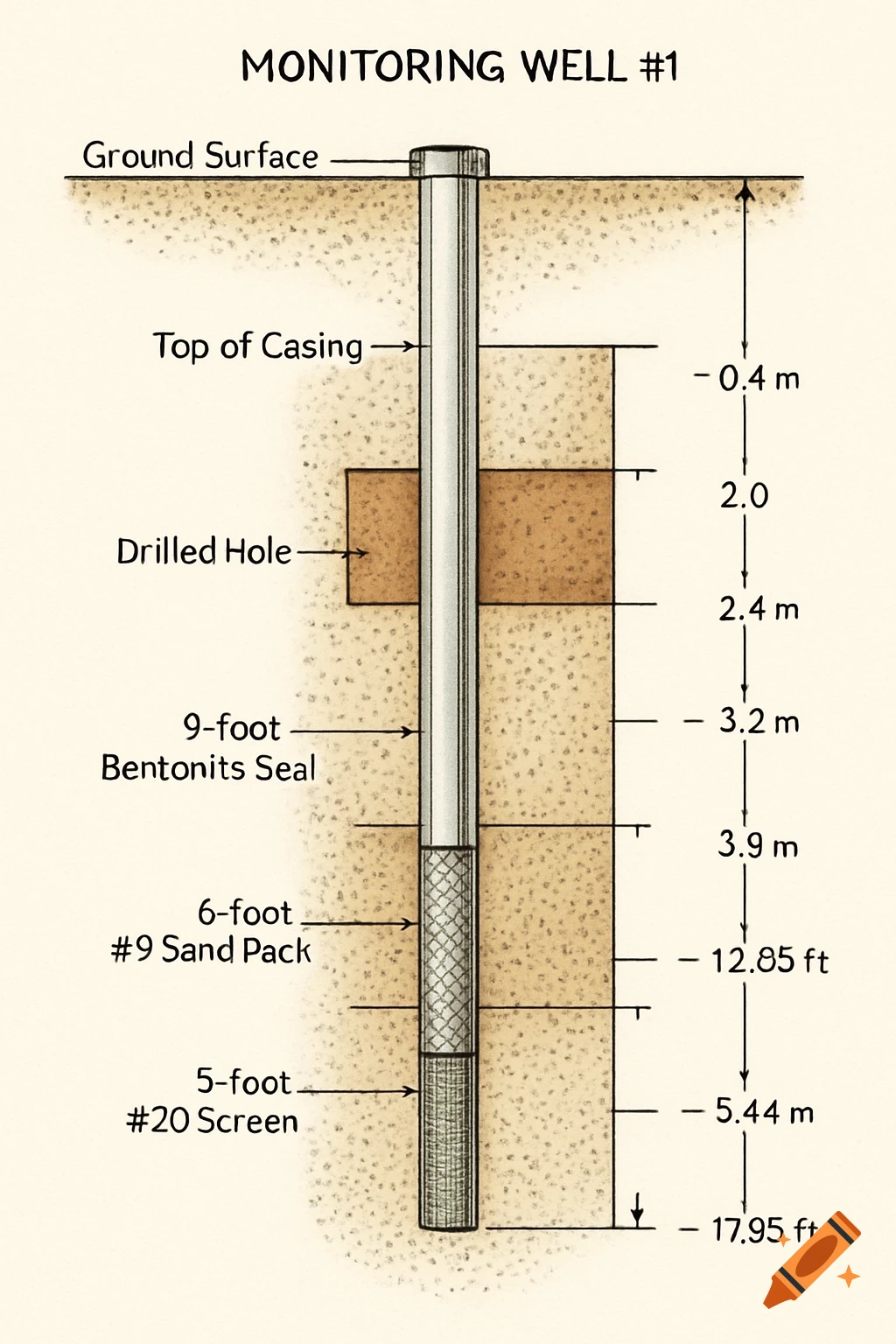
Well Log Diagram for Monitoring Well #1 This diagram should be a vertical cross-section of the well, drawn to scale, with depth measurements along one side. Start with the Ground Surface: Draw a horizontal line to represent the ground surface. Label this as "Ground Surface." Indicate the "Top of Casing" (TOC), which is your reference point for measurements. It is typically a few inches above the ground. Draw the Well and Borehole: The entire drilled hole (the borehole) has an intake diameter of 4 inches. Draw this as the outer boundary of your diagram. The well casing itself has an inner diameter of 2 inches. Draw this as the inner column inside the borehole. Label the Soil and Well Components by Depth: The total depth of the well (Z) is 5.44 meters (or 17.85 feet). Mark this point at the bottom of your diagram. The screen is 5 feet long with a size of #20. It is situated at the bottom of the well. Label the screen interval from the total depth (5.44 m or 17.85 ft) to 5 ft (1.52 m) above that. So, the screen would extend from 17.85 ft down to approximately 12.85 ft. The sand pack is 6 feet long with a grain size of #9. This sits around the screen. Label the sand pack interval, which will be the screen's interval plus the extra foot above it, extending from the total depth to 6 ft (1.83 m) above that (from 17.85 ft down to approximately 11.85 ft). The bentonite seal is 9 feet long. This sits on top of the sand pack. Label the bentonite interval, extending from the top of the See more